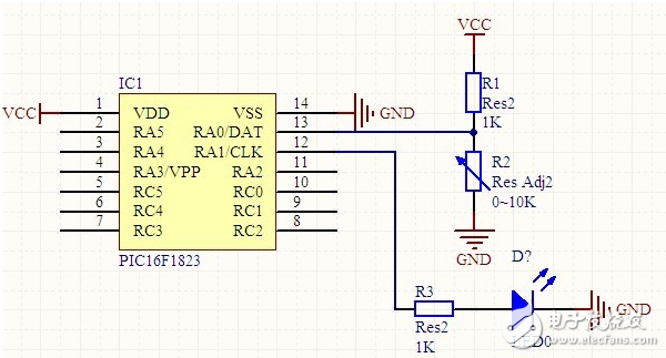
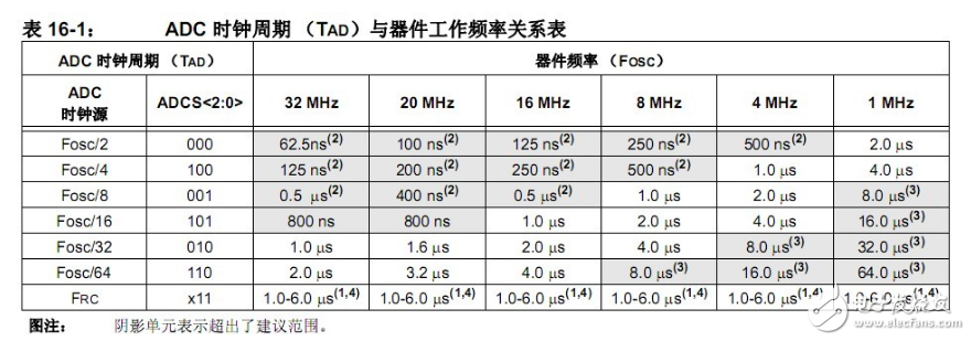
AD conversion is analog to digital conversion. As the name implies, it is to convert an analog signal into a digital signal. It mainly includes integral type, successive approximation type, parallel comparison type/serial parallel type, Σ-Δ modulation type, capacitor array successive comparison type and voltage frequency conversion type. The A/D converter is used to convert analog quantities into digital quantities through a certain circuit. The analog quantity can be an electrical signal such as voltage or current, or a non-electrical signal such as pressure, temperature, humidity, displacement, and sound. However, before the A/D conversion, the input signal input to the A/D converter must be converted into a voltage signal by various sensors through various sensors. The PIC uses the number of ten bits to represent the voltage, which is the value 0~1023 to indicate the voltage. For example, if the value is 400, what is the voltage? This is determined based on the reference voltage. For example, we set the positive reference voltage to 3.3V. When the input voltage is 0, the value is 0. When the input voltage is 3.3V, the value is 1023. If the input voltage is 1.2V, how much voltage is represented. First, first calculate how much a voltage represents 3.3V divided by 1023, which is equal to 0.003V. Then, 1.2V divided by 0.003V is equal to 400. This gives 400 representing 1.2V. See the figure below. We can see AN0~AN7. These are the ports that can be configured as analog inputs. Only these pins can be used as ports for AD conversion. For example: the following schematic diagram, input an analog quantity from the RA0/AN0 pin. If the voltage is greater than 1.2v, the LED will be on or the LED will be off. Set the RA0 port to input TRISA = 0x01; Set RA0 port to analog ANSELA = 0x01; How to choose the conversion clock should be based on the current clock frequency. You can choose according to the table in the data sheet. We set the clock frequency of the MCU to 32MHZ. Do not select the shadow part of the ADC cycle key. In the 32MHz column, we randomly select the ADC clock cycle of 1us, the corresponding clock source is Fosc/32., AD control register 1 ADCON1 ADCS "2 :0》=010 Note: ADCS "2:0" means 0 to 2 bits of ADCS. We choose right alignment here, so ADAD=1 of AD control register 1 ADCON1 The configuration of the ADCON1 register is finished above. Let's explain ADCON0 There is only one AD conversion module, and the AD input channel has 8 AN0~AN7. Therefore, it is impossible to perform AD conversion at the same time. The one that needs to be assigned to us is to assign the AD conversion module to AN0 according to the hardware. So the CHS "4:0" of ADCON0 = 0000; The ADC module is turned on, ADON=1 of ADCON0, but the ADC module is simply enabled. Does not start AD conversion. It is recommended to turn off if the ADC module is not used. You can save some electricity! ! ! ADCON0 GO/DONE=1 turns on AD conversion. In general, we do not take the value of the AD conversion once. Instead, count the average after taking multiple times. This ensures the accuracy of the conversion. There are many places to configure the ADC module, and there is no explanation for why this configuration, because many configurations are actually quite random. Not so absolute. Must choose which one. Of course, the actual configuration is still based on your project needs. / / Development environment MPLAB X IDE, microcontroller PIC16LF1823. #include 《pic.h》 __CONFIG(FOSC_INTOSC&WDTE_OFF&PWRTE_ON&MCLRE_OFF&CP_ON&CPD_OFF&BOREN_ON &CLKOUTEN_OFF&IESO_ON&FCMEN_ON);//This is going to the previous line. __CONFIG(PLLEN_OFF&LVP_OFF) ; #define ADC_NUM 8 //Number of conversions #define LED LATA1 Void init_GPIO(void) { TRISA = 0x01; / / port is set to input ANSELA = 0x01; / / set to analog input PORTA = 0x00; LATA = 0x00; } Void init_fosc(void) { OSCCON = 0xF0; // 32MHZ } Void init_AD(void) { ADCON1 = 0xA0; / / right aligned, AD clock is Fosc / 32, the reference voltage is the power supply voltage, ADCON0 = 0x00; / / select channel AN0 ADCON0bits.ADON = 1; / / open the module } Unsigned int ADC_BAT_ONE(void)//converted once { Unsigned int value; Value=0; ADCON0bits.CHS =0; / / select channel AN0 ADCON0bits.ADGO=1;//Start conversion While(ADCON0bits.GO==1);//waiting the end of the conversion Value=(unsigned int)ADRESH;//Forced type conversion, because ADRESH is a character type and can only represent 8-bit binary. So it must be converted to an integer that can hold a 10-bit binary. Value= value "8;// shift the upper two digits to the left by 8 digits Value += ADRESL; // The lower eight bits add the value of ADRESL. Return value; } Unsigned int ADC_BAT_contiue(void) { Unsigned int ADV_MCU[ADC_NUM], ADV_CNT, ADV_ALL; ADV_ALL=0; For(ADV_CNT=0; ADV_CNT "ADC_NUM; ADV_CNT++) / / perform multiple AD conversion { ADV_MCU[ADV_CNT]=ADC_BAT_ONE(); } For(ADV_CNT=0;ADV_CNT“ADC_NUM;ADV_CNT++)//calculate the average of multiple AD conversions { ADV_ALL += ADV_MCU[ADV_CNT]; } ADV_ALL= ADV_ALL/ADC_NUM; Return ADV_ALL; / / get the result back } /* * */ Int main(int argc, char** argv) { Init_fosc();//Set the clock init_GPIO();//Set I/O port init_AD();//Set AD While(1) { If ( ADC_BAT_contiue () " 400) / / determine whether the input voltage is greater than 1.2V { LED=1; / / light is on } Else { LED=0;//lights off } } } Air Umbilical Winch,Pneumatic Umbilical Winch,Pneumatic Power Air Winch,Pneumatic Umbilical Air Winch RUDONG HONGXIN MACHINERY CO.,LTD , https://www.rdhxmfr.com


