In order to solve the problem of heat generation and burnout during the use of the motor, it is necessary to detect the motor current to achieve current limiting protection of the motor. Combined with the actual situation of industrial enterprise production, based on the mathematical model of motor overcurrent protection, the inverse time overcurrent protection scheme for PLC is proposed, and the software and hardware design of the scheme is given. The motor protection performance of this program has been verified in actual production. Insulated Terminals,Terminals,High-quality insulated terminals Taixing Longyi Terminals Co.,Ltd. , https://www.txlyterminals.com
Large-capacity motors are used in the production of industrial enterprises. Due to the long-term continuous operation of these motors and long-term effects of dust and current changes in the production environment of the enterprise, the motor is prone to heat. If the motor does not exceed the defined calorific value, it can operate safely. If the calorific value exceeds the limit value and the motor continues to run for a long time, the motor temperature will gradually increase, resulting in lower motor performance and even burnt the motor, thus heat the motor. Protection is very important. The reason why the motor is hot is usually caused by the current exceeding the rated value. The transient current is too high during startup, but the continuous overcurrent must be reduced within a limited time. Otherwise, the power-off circuit needs to be activated to protect the motor. That is to say, the essence of motor thermal protection is to determine the overcurrent nature of the motor.
1 Motor anti-time limit overcurrent protector development trend
Inverse time overcurrent protection can be understood as the protection action time varies with the motor current. There are two key points: First, the motor current exceeds the rated current for a specified time, the protection will be activated; second, the larger the motor current, the shorter the protection action time. Experts from all over the world are studying this type of protection. The earliest use of conventional bimetal thermal relays, the inverse time overcurrent protection circuit designed by analog circuits in the 1970s and 1980s, and the powerful intelligent instruments after the 1990s. Modern enterprises are PLC-based motor protection systems. The shortcomings of the conventional bimetal thermal relay are unreliable and unstable. The inverse time overcurrent protection circuit of the analog circuit design is an overcurrent protector designed by capacitor constant current charging. The disadvantage is that the circuit design is complicated, the versatility is poor, and the electronic There are many devices, and the sampling accuracy of the motor protector with the single chip as the core has a qualitative leap. The sampling accuracy of the motor protection system with the core of the PLC is further improved.
2 Establish a mathematical model of motor inverse time overcurrent protection
When the motor is running normally, the heat generated by the motor and the amount of heat dissipated by the motor can reach the thermal balance. The continuous operation of the motor will not burn out and the protection circuit will not start. Let Ie be the rated current value of the motor, and the rated current heat during the time period t is 
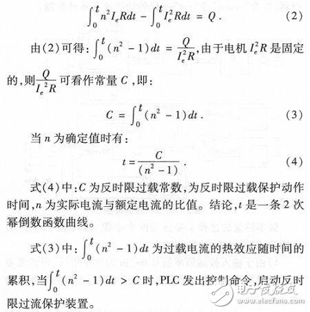
When the motor is overloaded, the magnitude of the current is not constant, but the actual current may be different at different times. The thermal effect of the overload current accumulates with time, and the overload heat is integrated over time. Therefore, equation (1) can be expressed as: 
Equation (3) is only applicable to the change in thermal effect at 1.05 ≤ n ≤ 7. There are two kinds of situations in actual use, one is when 
Figure 1 Inverse time overcurrent protection curve
The computer can only process discrete data, and the integral form of equation (3) is a continuous curve. Therefore, the discretization of equation (3) is processed:
The number of times the heat is summed before starting is N. The sampling interval is Δt, and the duration of the cyclic interrupt OB38 is 100 ms. Since Δt is small, the sampling current is basically unchanged. When the accumulated heat is less than C, the overload lock is cleared and the motor is restarted.
Program implementation: According to industry standards, considering the different heat accumulation speed, different heat dissipation speed, combined with actual and on-site ventilation and heat dissipation, after repeated calculation and testing, adjust the parameter C in the mathematical model, and finally improve the anti-time limit over-current protection accuracy of the motor. Determine to adopt:
3 design block diagram of motor inverse time overcurrent protection scheme
The main controller of this solution selects PLC because it has the advantages of easy expansion, low failure rate, high stability and high reliability.
The motor protection system consists of two parts: hardware and software.
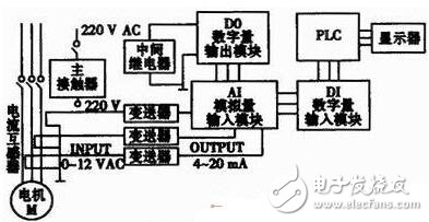
The hardware mainly includes the main control computer, analog-to-digital conversion module, control contactor and analog signal extraction. The main control computer is composed of the main controller PLC (siemens programmable logic controller PLC), keyboard, mouse and display. The control contactor is composed of intermediate relay and main contactor. The analog signal extraction is composed of current mutual inductance and transmitter. The analog-to-digital conversion module is composed of an external extended digital output module DO, a digital input module DI, and an analog input module AI. The hardware design block diagram is shown in Figure 2. 
Figure 2 hardware design block diagram
The software part is programmed in the STL language of STEP7 software.
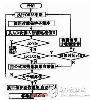
Design ideas: First, measure the current current value; second, segment according to the current overload multiple; third, calculate the protection time according to the real-time current change (according to the current overload multiple); fourth, the fixed time delay protection.
Design Disadvantages: This is a cumulative process of time. It can only estimate the change of heat, and it can not reflect the real-time change of heat of the motor (ignoring the temperature rise process of current rise). The flow chart of the program needs to be repeated and tested as shown in Figure 3. 
Figure 3 software flow chart