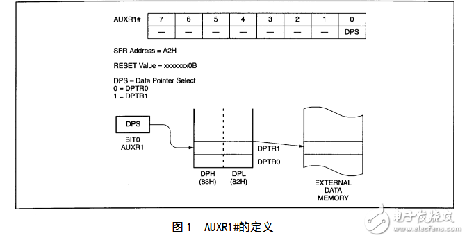
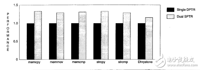
DPTR is a special function register in some microcontrollers. It is a 16-bit special function register. Its high byte register is represented by DPH, the low byte register is represented by DPL, and DPTR can be handled as a 16-bit register. Can also be used as two independent 8-bit registers The main function is to store a 16-bit address. As an address register for in-chip RAM addressing (indirect addressing), it is called a data pointer. It can also transfer the contents of the address in the external RAM to the contents pointed to by the address of the internal RAM. The addresses of DPH and DPL are 83H and 82H, respectively. In the process of redesigning the program upgrade, the 51 series MCU adds another data pointer DPTR. Software can use additional data pointers to speed up program execution and reduce program size The beginning of this article outlines the operation of the original data pointer and then briefly describes how the new data pointer matches the original data pointer. This article also explains the physical and software identification of the double data pointer part. Finally, various software strategies including dual data pointers are included. Assembly language interrupt and C are explained In the Intel MCS-51 microcontroller architecture, the 16-bit DPTR register can address various parts of the memory area. The instructions for using the DPTR addressing memory are as follows. MOVX @DPTR, A sends the contents of accumulator A to the data memory area addressed by DPTR. MOVX A@DPTR sends the contents of the data memory area addressed by DPTR to accumulator A. The 8051 structure uses the pins PSEN and RD respectively to gate the program memory read-only and the data memory MOVX instruction to access the data memory (for example, the RD pin data memory generally refers to RAM or memory image I/O). MOVC A@DPTR sends the contents of the program memory area addressed by DPTR to accumulator A The MOVC instruction transfers access to a read-only constant (for example, a data table string) by accessing a program memory such as the PSEN pin. The program memory generally refers to the ROM or EPROM JMP @A+DPTR transferred to the contents of the DPTR and A. Addition address The address formed by the addition is not changed. The PC registers DPTR and A are not changed. This instruction is often used to perform the table lookup function. The base address of the DPTR pointer table in the table is indexed by A. The instruction to operate the DPTR is as follows. INC DPTR DPTR plus 1 MOV DPTR#16 sends 16-bit immediate data to DPTR However, DPTR is also manipulated as a special function register SFR with other CPU registers such as ABPSW. All special function registers access bytes through various instructions such as PUSH and MOV and use direct addressing. The 16-bit DPTR can be mapped into two special function registers for byte addressing. The two special function registers are DPH high byte address 83H and DPL low byte address is 82H instruction as follows MOV DPTR#1234H with immediate 1234H loading DPTR Its function is equivalent to executing the following two programs but the time and program size of the execution program are not equal. MOV DPH#12H Send the immediate number 12H to the DPTR high byte 83H MOV DPL#34H Send the immediate 34H to the DPTR low byte 82H The following 51 series CPUs are upgraded by using dual data pointers. P8xC51P8xC52P8xC54P8xC58 Contact Philips Semiconductors to determine the conversion status of the dual data pointers for these and future products. See Figure 1. These upgraded CPUs still have only one logical data pointer but can be split into two physically separate data pointers. For example, by using DPTR as an operand instruction, the current selected data pointer can be accessed according to the state of the DUX bit of the AUXR1 special function register address A2H to determine the index of DPH83H and DPL82H using one of the physical data pointers similarly SFR. . DPS is set to 0 at reset so that any value can be written to the undefined bit in DPSAUXR1. However, the read operation can only be 1CPU whether a single data pointer or a double data pointer can be determined by detecting the current value of the DPS bit. The following is a special description of the 80C51 AUXR1 special function register for 80C51. The format of the new 80C51 AUXR1 with double data pointer is slightly different from the above AUXR1 format. Figure 2 shows that bit 3 is the wake pattern from the low power mode. Select Bits When reset, WUPD and DPS are set to 0. The application that uses the CPU power-down mode can set WUPD to 1 after reset. Enable wake-up characteristics. Bit 2 is defined as 0 for easy handling of DPS bits as described in the following section. Figure 2 Definition of AUXR1# 80C51 Additional data pointers can speed up program execution and reduce program size in many ways, such as by using one data pointer as the source pointer and the other as the destination pointer to handle many common block operations such as copy comparison searches. ------------------------------------------ Block moves using double data pointers Destroy DPTR0DPTR1A and PSW Note that the state of the DPS exit is the opposite of the state at the time of entry unless the additional INC AUXR1 instruction is added. ----------------------------------------- 00A2 AUXR1 EQU 0A2H 0000 909000 MOV DPTR#SOURCE Use DPTR source address 000305A2INC AUXR1 Switch data pointer 0005 90A000 MOV DPTR#DEST Use DPTR to save the destination address 0008 LOOP 0008 05A2 INC AUXR1 Switching Data Pointer 000A E0 MOVX A@DPTR Byte 000B A3 INC DPTR from source address Increase source address 000C 05A2 INC AUXR1 Switch data pointer 000E F0 MOVX @DPTRA Write byte 000F to the destination address A3 INC DPTR Add destination address 0010 70F6 JNZ LOOP Check if 00012 05A2 INC AUXR1 Optional restore DPS The DPS bit INC for processing AUXR1 is a command that is 2 bytes shorter and executes 12 clock faster. However, the INC instruction cannot directly put the DPS bit into the participating state but simply switches the DPS bit in a simple program operation. Block move DPS bits are simply switched in the proper order instead of passing it In fact, the value of the DPS bit is 0 or 1 when the block move operation ignores the entry. Note that if there is no last instruction, the INC AUXR1 program will exit when the DPS is in the opposite state. For the 80C51 bit 2 defined as 0, the repeated INC operation will not propagate the last value of bit 2 and will not affect the WUPD bit. In some cases, such as error recovery or interrupt, only switching DPS bits is not enough. DPS must be set to a known value and this value is independent of the current state. 53A27E ANLAUXR1#7EH DPS=0 43A201 ORLAUXR1#1 DPS=1 Each instruction takes up 3 bytes and 24 clocks Another case where an additional data pointer is used is to process one or more interrupts with a data pointer. In the conventional way, for example, a single data pointer handler must store an entry. The current value of the DPTR is typically stored in a register or stack. The DPTR is loaded with the value of the processor. Reverse processing on exit Now in the typical foreground and background interrupt modes, each processor can use the data pointer alone. By switching off the instructions with a single data pointer, switching between data pointers can speed up the interrupt response and reduce the program size. In more cases, these situations include having two interrupt handlers and/or using two data pointers in more than one processor. Data pointers can be shared using the same method as traditional single data pointers for storing and restoring DPTR. The scheme can generally be implemented by addressing the SFR so that any instruction that supports direct addressing modes such as PUSH or MOV can be used. In some cases, such as interrupts or subroutine calls, it is necessary to store the state of the DPS bit because interrupts or subroutine nesting will destroy the DPS when using DPTR by using any instruction that supports direct addressing mode such as PUSH or MOV. AUXR1 Special Function Register Can contain DPS to be stored and restored These techniques are applied to the block move example. The contents of the two data pointers are stored and restored. The content of the APSR1 does not need to be accurately stored because the DPS value of the block move program is equivalent to the value of the entry when exiting. -------------------------------------- Block mover uses double data pointers This program can store and restore the state of the data pointer Destroy only A and PSW ------------------------------------- 00A2 AUXR1 EQU OA2H 0000 C083PUSH DPH saves the first data pointer 0002 CO82PUSH DPL 0004 909000 MOV DPTR#SOURCE Use it to store the source address 0007 05A2INC AUXR1 switching data pointer 0009 C083PUSH DPH saves the second data pointer 000B C082PUSH DPL 000D 90A000MOV DPTR#DEST Use it to store the destination address 0010 LOOP 0010 05A2INC AUXR1 Switch Data Pointer 0012 E0MOVX A@DPTR fetches bytes from the source address 0013 A3INC DPTR increase source address 0014 05A2INC AUXR1 Switch Data Pointer 0016 F0MOVX @DPTRA Writes bytes to the destination address 0017 A3INC DPTR increase destination address 0018 70F6JNZ LOOP judges whether it is 0 001A D082POP DPL restores the second data pointer 001C D083POP DPH001E 05A2INCV AUXR1 Switch Data Pointer 0020 D082POP DPL restores the first data pointer 0022 D083POP DPH The operation of the C compiler is not affected by the additional data pointer. Assuming that the DPS bit does not change after RESET, the C program will continue to use the single data pointer. In many cases the program mix contains C and assembly language using the currently discussed technology assembly language parts such as regular library entry interrupt handlers, etc. can be upgraded without affecting the C compiler using the first data pointer in the case of assembly language Use the second data instruction The application written in 'C' has many advantages. It uses double data pointers to make the compiler upgrade. As shown in Figure 3, the performance improvement by modifying the block orientation COPY and MOVE library programs is obvious. The code is about 15-30% later. Optimized generator and parameters for better performance improvements Figure 3 Performance improvement of dual DPTRC Portable Battery ,Portable Power Bank,Portable Battery Pack,Portable Power Pack Zhejiang Casnovo Materials Co., Ltd. , https://www.casnovo-new-energy.com

