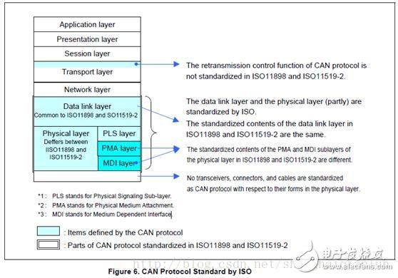
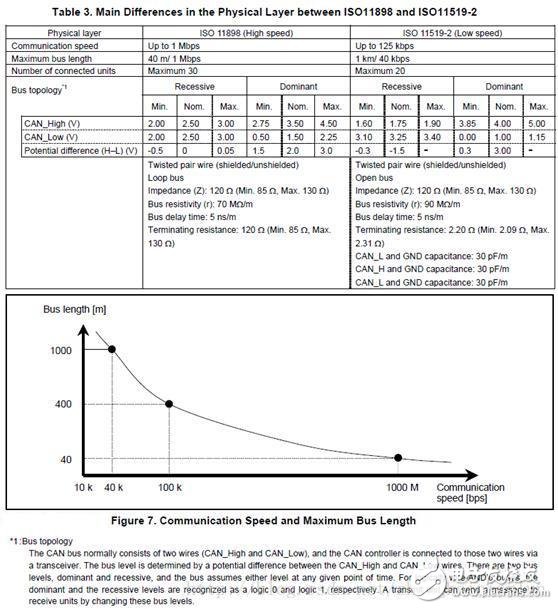
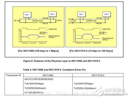
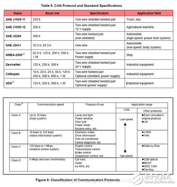
The CAN protocol has been standardized by ISO and has two versions, such as ISO11898 and ISO11519-2, which are no different at the data link layer, but differ in the physical layer. (1) About ISO11898: This standard is used for high-speed CAN communication. In the beginning, the data link layer and the physical layer were specified in the standard ISO11898, and later split into ISO11898-1 (data link layer only) and ISO11898-2 (physical layer only) (2) About ISO11519: This standard is used for low speed (up to 125kbps) CAN communication Figure 6 shows the specified range of the CAN specification. Sublayers of three physical layers: PLS (Physucal Signaling Sublayer) sublayer, PMA (Physical Medium Attachment) sublayer, MDI (Medium Dependent Interface) sublayer, PMA and MDI sublayer The definition is not the same. Table 3 lists the differences in physical layers between ISO11898 and ISO11519-2. Figure 7 shows the relationship between communication speed and bus length. Communication speed and bus length need to be set by the user according to system requirements. Bus topology: The CAN bus usually consists of two lines (CAN_High and CAN_Low). The CAN controller is connected to the bus through a transceiver. The level of the bus is determined by the potential difference between CAN_High and CAN_Low. The bus has two levels: dominant and Implicit, the bus is always at one of these 2 levels at any given time. For a logical "wire-to-wire" bus, the dominant and recessive levels are treated as logic 0 and logic 1, and a transmitting unit can send a message to the receiving unit by changing the bus level. The physical layer termination impedance, dominant level, and recessive level differential voltage specified by ISO11898 and ISO11519-2 are different. Figure 8 shows the characteristics of the ISO11898 and ISO11519-2 physical layers. Note that ISO11898 and ISO11519-2 require a transceiver to meet the corresponding standards. Table 4 lists the main transceiver ICs that meet ISO11898 and ISO11519-2. In addition to ISO, CAN specifications are standardized by industry standards organizations such as SAE, and are standardized by a number of private research institutions and companies. Table 5 except for some basic standard specifications, Figure 9 shows the communication protocol for cars classified according to communication speed SAE: on behalf of the Society of Automotive Engineers (Society of AutomoTIve Engineers) NMEA: On behalf of the National Association of Marine Educators (NaTIonalEducators AssociaTIon) SDS: Represents SmartDistributed System Class: Category name of SAE Multi function remote manual pulse generator for control of all axes. Manual Sensor,Miniature Optical Kit Encoder,Rotary Encoder With Led Ring,Optical Quadrature Encoder Yuheng Optics Co., Ltd.(Changchun) , https://www.yuhengcoder.com


Overview of CAN protocols and standard specifications
CAN protocol and standard specification 1. CAN protocol standardized by ISO