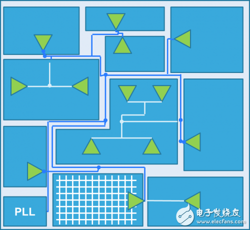
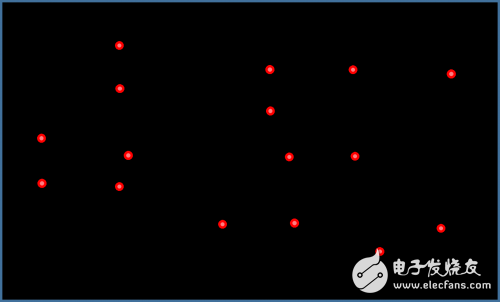
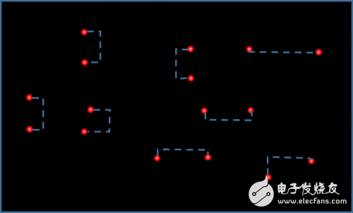
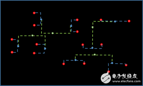
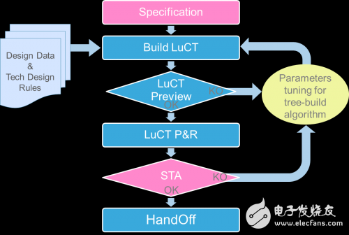
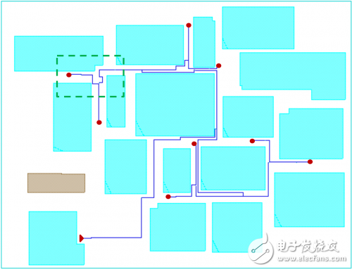
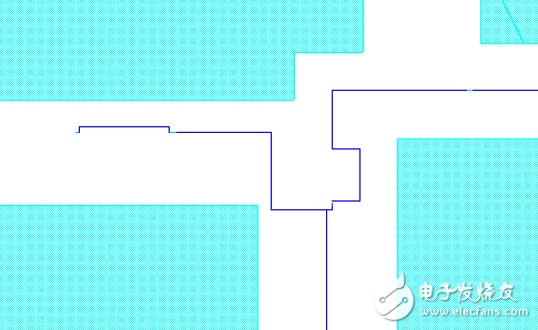
What is LUCT? First layer clock tree and second layer clock tree The clock tree design and its design method are the main reasons for the difference in system chip performance. Historically, ASIC clock tree designers have used commercial automation tools to design clock trees to ensure that performance such as execution time achieves the desired results. However, the clock skew and insertion delay of this method are not satisfactory, and high. Complexity, frequency and size design make traditional methods completely unfeasible. The low uncertainty clock tree [LUCT] design and algorithm is related to the physical definition of the first layer of clock tree implemented on the system chip, allowing designers to overcome all the inefficiencies of traditional design methods. From the top-level root clock network (usually the PLL output) to the mid-level clock network, LUCT is a high-quality load-balanced clock tree with the goal of sending clock signals from the central phase-locked loop PLL to most areas of the chip. See reference [1]. This document details the low uncertainty clock tree [LUCT] method and architecture, summarizing all relevant design flows from specification definition to cell layout and clock synthesis. According to the definition of reference [2], this clock distribution method belongs to a structured clock tree. The literature [2] also outlines the different clock design methods available. From the clock source to the register, the entire clock tree consists of a first layer clock tree and a second layer (or local) clock tree. Commercial EDA tools need to implement a local clock tree. LuctGenKit is a clock design tool developed by the design methodology team at STMicroelectronics' Digital ASICs product group to complete the physical implementation of the LUCT architecture. Figure 1: Optimizing Clock Distribution in ASIC Design Main features of LUCT tools The LuCT clock synthesis tool provides all the important features of the LuCT method: o Balanced clock tree - Length equal and active load matching - Obstacle perception - Signal transmission using a low-resistance high-rise metal layer - Shielding and parasitic matching o Enhanced custom cell library for a variety of signal strength requirements o Support a variety of manufacturing processes, for example, 32/28bulk, 28fdsoi, etc. o Module layout, obstacle layout and obstacle avoidance o Fully integrated with the place and route environment LuCT design flow Figure 2: LuCTgenKit design flow The LuCTgenKit design flow is divided into four phases, which are discussed in detail in the following sections of this article. This tool simplifies complex ASIC design and is especially effective in design environments where multiple engineers are involved in the physical implementation of the entire project. Within a typical design organization, the initial stages of physical implementation are database preparation and specification definitions. The final phase of the work is primarily done by dedicated LuCT engineers. Once the database preparation and specification definitions are complete, only one LuCT design engineer can complete the implementation and finalization of the entire top-level clock tree (perhaps more than one clock tree) within one business day. LuCT tool database preparation Database preparation includes necessary design checks, layout planning plausibility verification, reading power grid shape properties, and place and route tools. Among them, the place and route tool is used to connect to a special enhanced clock library, and the clock library layout is ensured through the LuCT creation algorithm. This phase is also a key step in enabling structured clock trees to take advantage of existing technologies to achieve maximum performance, especially in terms of reducing voltage drop and resistance to crosstalk. LuCT tool LuCT specification definition For each clock synthesis, you need to enter the following information in the tool: o Technology node o Primary clock tree starting point (PLL) - X and Y coordinates o Main clock tree end point - X and Y coordinates on each leaf o Frequency range o Process - voltage - temperature angle o Clock unit parameter selection Designers can enter all the data and design methods they need through a graphical user interface. LuCT tool execution: Create LuCT The low uncertainty clock tree synthesis automation tool bundles the following objects: - Design specifications - Layout planning information (including layout barriers and wiring barriers) - Power grid - Design and layout rules - Netlist - layout - GUI - Report - Finalize Figure 3: LuCT Application Software Graphical User Interface Menu The LuCT tool generates a clock tree topology using algorithms unique to STMicroelectronics. The algorithm is based on equalized path lengths and equal length homogenous wiring. The Lemon C++ graphics library [4] is required for chip layout planning modeling and initialization as well as path computation. The clock tree creation process consists of the following steps: o Grid generation: After reading data from the layout plan, generate the obstacle model and the power grid shape model. From these models, a set of points (grids) representing the placement and routing pitch defined by the LuCT algorithm is calculated. o Building a binary tree: Grouping leaves using ST's unique algorithm, one pair per group. Each pair of leaves is merged by calculating a path of equal length including the obstacle avoidance point and a merge point (ie, a point in the middle of the path). In this way, new leaves (merging points) are merged recursively until only one point (tree root) remains, as shown in Figure 4 through Figure 6. o Insert clock driver and routing: Inserting the clock driver and optimizing the routing is a bottom-up approach that considers barrier layout and barrier routing, respectively. Figure 4: Endpoint set Figure 5: LuCT tree creation algorithm pairing decision and merge Figure 6: Consolidation of merge points generated by the previous level Figure 7: Design flow with LuCT tools Once the clock tree structure is generated, the layout can be implemented using a script within the Place and Route CAD tool. For high-performance routing/wiring, via layout, and power-noise-aware layouts for multiple parallel clock drivers, custom layout rules are required to achieve layout configuration. The algorithm can be optimized by modifying several parameters that have a large impact on the binary tree architecture and creation. Here are some examples of parameters: o Leaf pair generation: can be generated automatically or manually o Path distance calculation: can be pure Manhattan mode or can sense obstacles o Minimize bending: choose the right attractiveness for the cabling network o Attracting the merged area to the current center by re-mapping the center globally in each cabling/merging phase o Clock tree performance metrics: barrier strength, clock skew/insertion delay performance and barrier balance, clock congestion. LuCT tool examples and results Figure 8 shows the clock tree for designing a 28FDSOI chip using LuCTgenKit in accordance with the method discussed above. The 1 GHz clock signal is distributed from the clock source to 8 leaves, avoiding obstacles, balancing clock skew, and detecting obstacles. Figure 9 shows how the equal length calculation is performed when connecting high-level leaf pairs. Figure 8 Figure 9 The main conclusion of this example is that the clock skew is very limited according to the base delay calculation, however, a large number of uncommon paths occur. 12 Coaxial Speaker,Coaxial Speaker 12 Inch,12 Inch Coaxial Speaker,Pro Audio Coaxial Speakers Guangzhou Yuehang Audio Technology Co., Ltd , https://www.yhspeakers.com