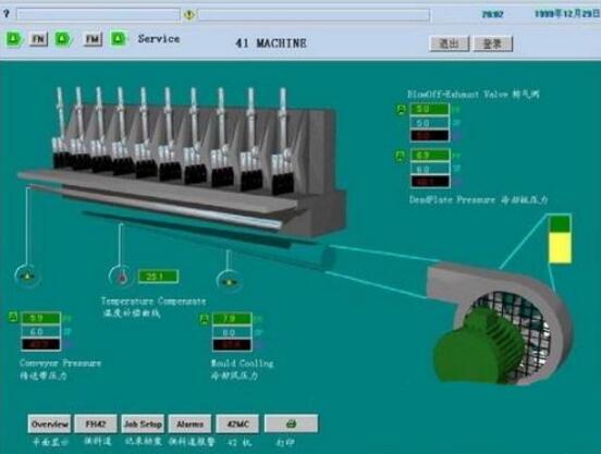
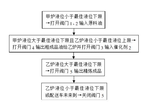
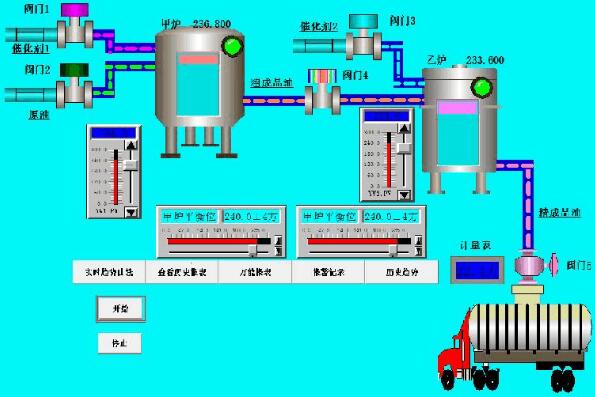
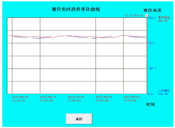
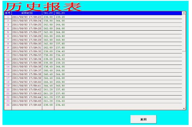
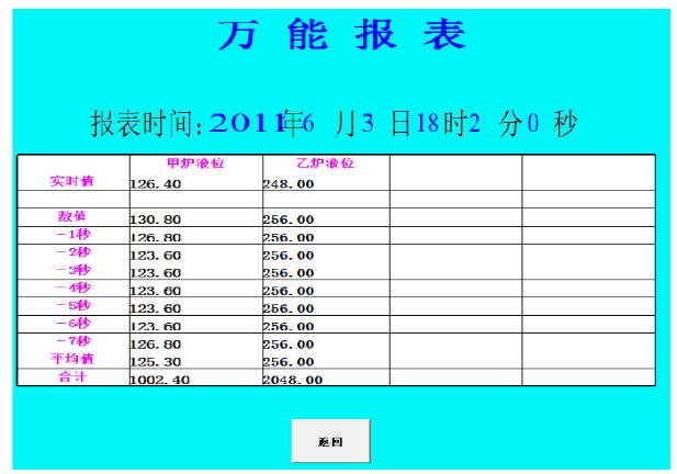
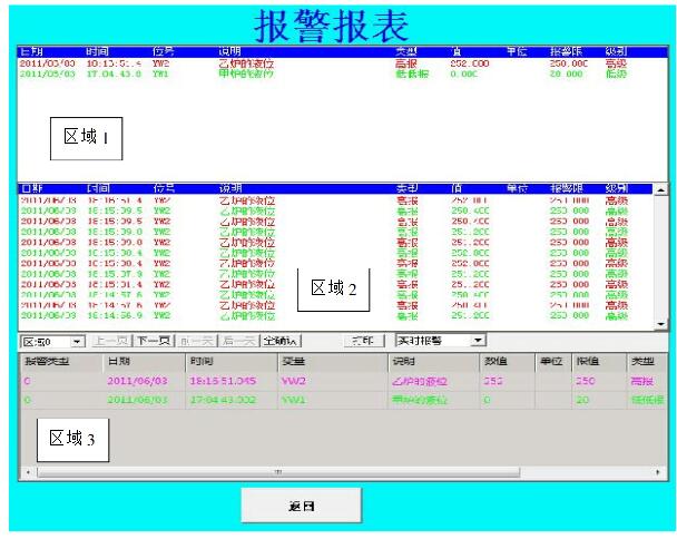
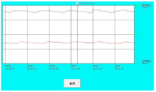
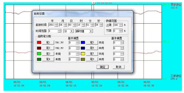
The configuration software refers to some special software for data acquisition and process control. They are the software platform and development environment at the level of the monitoring layer of the automatic control system. Using flexible configuration methods, users can quickly build monitoring functions of industrial automatic control systems. , general-level software tools. The configuration software should be able to support a variety of industrial equipment and common communication protocols, and should generally provide distributed data management and network functions. The configuration software refers to some special software for data acquisition and process control. They are the software platform and development environment at the level of the monitoring layer of the automatic control system. They can provide good user development in a flexible and diverse configuration mode instead of programming. The interface and the simple use method, the preset various software modules can realize and complete the functions of the monitoring layer very easily, and can support the computer and I/O products of various hardware manufacturers at the same time, and the high reliability industrial control The combination of computer and network system can provide all interfaces of software and hardware to the control layer and management layer for system integration. With its rapid development, real-time database, real-time control, SCADA, communication and networking, open data interface, and extensive support for I/O devices have become its main content. With the development of technology, the monitoring configuration software will Constantly being given new content. Corresponding to the concept of the original HMI (Human Machine Interface), the configuration software should be a software tool or development environment that enables users to quickly build their own HMI. Before the emergence of the configuration software, users in the industrial control field can write HMI applications by hand or by a third party, which has long development time, low efficiency and poor reliability. Or purchase a dedicated industrial control system, usually a closed system. To meet the demand, it is difficult to interact with the outside world, and upgrades and added functions are severely limited. The emergence of configuration software frees users from these dilemmas, and can use the functions of configuration software to build a set of application systems that are most suitable for them. The configuration software is professional. A configuration software can only be adapted to a certain field of application. The man-machine interface generation software is called the industrial control configuration software. In fact, there are configuration concepts in other industries, people just don't call it. For example, AutoCAD, PhotoShop, and Office Software (PowerPoint) have similar operations, that is, using software-provided tools to form their own work, and save the work as a data file instead of executing the program. The data formed by the configuration can only be identified by its manufacturing tools or other special tools. But the difference is that the configuration results formed in industrial control are used for real-time monitoring. The interpretation engine of the configuration tool is run in real time based on these configuration results. On the surface, the configuration tool runs the program to perform its own specific tasks. 1. Collect all I/O point parameters and fill out the form for use in monitoring configuration software and configuration on the PLC. 2. Find out the manufacturer, type, model, type of communication interface used, and the communication protocol used to make accurate choices when defining I/O devices. 3. Collect the I/O flags of all I/O points and fill in the form. The I/O flag is the keyword that uniquely determines an I/O point. The configuration software sends I/O to the I/O device. Identifies to request the corresponding data. In most cases the I/O identification is the address or tag name of the I/O point. 4. Draw and design the picture structure and picture sketch according to the process. 5. According to the table calculated in the first step, establish a real-time database and correctly configure various variable parameters. 6. According to the statistical results of the first step and the second step, a one-to-one correspondence between the real-time database variables and the I/O points is established in the real-time database, that is, the data connection is defined. 7. Configure each static operation picture (mainly drawing) according to the picture structure and picture sketch of the fourth step. 8. Establish an animation connection relationship between the graphic object in the operation screen and the real-time database variable, and specify the animation attribute and amplitude. 9, according to user needs, making historical trends, alarm display, and development of reporting systems. After that, you need to add security permission settings. 10. Segment and overall debug the configuration content, and modify the software accordingly according to the debugging situation. 11. After the whole content is debugged, the final software is finally improved (for example, the monitor screen is automatically turned on, the monitor screen is prohibited from being launched, etc.), and the system is put into formal (or trial) operation. Configuration software is a new type of software development tool that arises in the field of industrial automation. Developers usually do not need to write specific instructions and code, just use the tools in the configuration package, through hardware configuration (hardware configuration), data Configuration, graphic image configuration, etc. can complete the development of the required application software. In the process control experimental device, the boiler liquid level control is realized. In the past, the instrument was used as the regulator. The instrument changed the parameter value through the button of the instrument panel. There is no real-time data output curve, so the parameter adjustment is inconvenient and the control precision of the system. low. In order to change this situation, the boiler liquid level monitoring system was developed using Century Star configuration software, and data was collected and processed by computer. According to the real-time curve output of Century Star's boiler liquid level, the value of the parameter is changed by the sliding input block to stabilize the system output to the set value, thereby improving the working efficiency. The system has stable and reliable performance, friendly interface and strong scalability. The software design process of the monitoring system: (1) I understand that the distillation tower refining system mainly consists of two tower furnaces, which consist of two processes: a furnace refining + a furnace refining process, and adopts a refining method in which the refined oil is produced while the refining is performed. Liquid level refining, the workflow is as follows: (2) The configuration of the determined points is as follows: A furnace liquid level YW1 (analog input), B furnace liquid level YW2 (analog input), control valve one, two switches INT1 (digital input), control valve three, four switches OUT1 (digital Input), control valve five switch OUT2 (digital input), software monitoring system switch RUN. (3) After creating the monitoring center, draw the monitoring image as shown below and connect it to the animation. Description: The button in the figure left click to achieve its corresponding function, "Start" - the system starts running, "stop" - the system stops running, "real-time trend curve" - ​​go to the real-time trend curve window, "view historical report" â€â€”—Go to the historical report window, “Universal Report†– Go to the universal report window, “Alarm Record†– go to the alarm record window, “Historical Trend†– go to the historical trend window, “meter†– - Display the load of each delivery vehicle, the balance liquid level cursor of the furnace - adjust the optimal refining level of the refining furnace, and balance the liquid level of the furnace - adjust the optimal refining level of the B refining furnace, and the green indicator on the upper right of the furnace Light - high limit liquid level alarm indication. (4) Create a real-time trend curve window as shown below: Description: The horizontal axis shows the time, the vertical axis shows the two furnace liquid level values, the red curve is the furnace level, the blue curve shows the furnace level curve, and the left button clicks the “Back†button to return to the monitoring center window. (5) Create a historical report window as shown below: Description: Left click on the "Back" button to return to the Monitoring Center window. (6) Create a universal report window as shown below: Note: “Report Time:†displays the real-time time, and “Real-Time Value†shows the liquid level value of the A and B furnaces respectively. “Value, -1 second, -2 seconds, -3 seconds, -4 seconds, -5 seconds, -6 seconds, -7 seconds, average, total" respectively shows the liquid level values ​​of the furnaces in the current window, -1 second, -2 seconds, -3 seconds, -4 seconds, -5 seconds, -6 seconds, and -7 seconds. Their average and sum, left click on the "back" button to return to the monitoring window. (7) Create an alarm record window as shown below: Note: Area 1 shows the real-time alarm situation, Area 2 displays the historical alarm record status, Area 3 displays the real-time and historical alarm status of each area, left click the “Back†button to return to the monitoring window. It contains all the records, with page flipping and confirmation. (8) Create a historical trend window as shown below: Description: The horizontal axis shows the real-time time, the vertical axis shows the real-time trend curve of A and B. The red one is the furnace, the black one is the furnace, left click the “back†button to return to the monitoring window, drag the upper cursor to view each Time coordinate values, double-click the window to display the following trend setting window: 3, design experience and experience: Through this configuration software design, I mastered the configuration software for point configuration, making windows, making animation connections, writing scripts, making various reports, making real-time and historical alarm records, and debugging running projects. Software development operations. In addition, this design made me understand the powerful functions of the configuration software and its application in monitoring systems in various fields. 4. Personal advice: I personally think that teachers should reduce some theoretical time and add some experimental classes, because this course is focused on practical aspects. At the same time, I hope that the teacher will focus on the difficulties and biases of the mediation operation, because some simple operations can be self-learned without the need for teachers to talk to students. Or give more examples of operations that use special operations or inactivity, so that students can imitate learning. Washing Machine Pcb,Washing Machine Pcb Board ,Washing Machine Board Pcb ,Washing Machine Pcb Board Repair Full Industrial CO.,ltd. , https://www.iotaindustrial.com